
30 LEDs with 30 Volts
I’m currently (quite lazily) realizing a medium-ish size project which aims to bring several of Mr. Carlson’s capacitor testing devices into one single device to speed up the testing process by not having to move the cap around across several different pieces of equipment (each of them also requiring power supply, casing, etc…).
Mr. Carlson (Paul) has designed and realized a leakage detector and a tester for detecting the which pole is connected to the external foil in non polarized poly type caps.
Both of Paul’s projects use for the User Interface a 10 LED dot-type meter based on the LM3914V IC using a slightly modified version (for 30V supply) of the “Operating with a High Voltage Supply” application from the datasheet.
It’s also my intention to add an ESR meter (more on that in some other post), a cap discharger and package that nicely into a project box with a linear power supply.
To be able to read the ESR with some degree of accuracy though, I want to increase the resolution of the display by adding more LEDs to the scale (and scale the signal accordingly at the display input).
This post is essentially about how to realize a 30 LED display meter which is powered by a 30V power supply by combining and extending the two applications “Operating with a High Voltage Supply” and “20-Segment Meter with Mode Switch” from the datasheet.
Understanding the applications in the datasheet
Before showing the circuit I came up with and the measurements, I’d like to show reasoning I did by breaking down the examples provided in the datasheet. This will help understanding the final desing.
Let’s start with the easy one: “20-Segment Meter with Mode Switch”
20-LED dot-mode display
In the schematic below (Fig. 1) I removed the switch between bar / dot mode to make it more readable.

The way dot mode carry is implemented, is described quite well in the datasheet so I’ll not talk about that here.
Like shown in Fig. 2, the way the two devices divide the input range between the two of them is also pretty easy to understand: the two internal voltage references are basically connected in series like in the diagram below and the two internal resistor dividers connected between RLO and RHI for each of the two devices will have the ranges 0V 🠒 1.2V assigned to the first LM3914V and the range 1.2V 🠒 2.4V assigned to the second one.
Additionally the resistors R1 and R3 would set the IL to ca. 10mA.

How to extend this to 30 LEDs is at this point fairly straightforward: one would need to add obviously another LM3914V, replicate the dot carry wiring, wind up the third voltage reference in series with the second (so that the third driver gets the portion 2.4V 🠒 3.6V) and provide a resistor with value 3.6KΩ to set the IL current also to 10mA. So far so good.
Operating with a high voltage supply
I made a post about this application so I’ll assume the reader is familiar with this application as well. If not please read the post before continuing.
Merging the two applications into one
The high voltage supply application shows that we need to let the LM3914V operate their output drivers in the saturation region and have the leds current set by the R2 resistor based on the formula
so let’s say we desire to have a current of 12mA.
The required power handling capabilities for R2 are given by
Also we need to make sure that we set the current flowing out of the voltage reference to ca. 2mA (corresponding to a desired ILED current of 20mA) to give us a margin for guaranteeing the region of operation of the LM3914’s drivers.
With this specification we can calculate the values for the three Vref resistors using Ohm’s law:
- $ R_{ref1} = (1.25V / 0.002A) = 620\Omega \approx 680\Omega $
- $ R_{ref2} = (2.50V / 0.002A) = 1240\Omega \approx 1.2K\Omega $
- $ R_{ref3} = (3.75V / 0.002A) = 1860\Omega \approx 1.8K\Omega $
(yes, although I should have approximated down to 560Ω, 680Ω is also fine)
With that sorted out, we need to make sure the supply voltage is adequately high to provide enough juice to the last LM3914 for it to provide a Vref of 3.75V.
I struggled a bit on this, thinking I had to adjust somehow resistor values or using some fancy technique to accomplish that but after the analysis of the high voltage supply application, the answer became clear and easy: I just had to connect the Vref3 to the base of the PNP so that basically the V+ would become 3.75V + VEB + VLED which is basically as high as 6.1V.
Last but not least I wanted (as Paul envisioned for his leak detector) the LED which is part of the V+ regulation, act as an “overflow” indicator for the display basically being dark when there’s at least one display LED ON and lit when all display LEDs are OFF. This requirement helps setting the value of resistor R1.
Let’s say we’re using a LED which looks almost completely dark at 0.5mA with a drop of 1.7V and it looks completely lit at 10mA with a drop of 2.1V.
This gives us the following calculation for R1 but not so easily… in fact we must supply current to 3 LM3914. At any given time one of those devices will have one LED turned on and the other two will have no LED turned on. Looking at the experimental results of the previous build I’d consider 10mA for the device which has the LED on and 9.7mA for the one which has all LEDs off.
The required power handling capabilities for R1 are given by
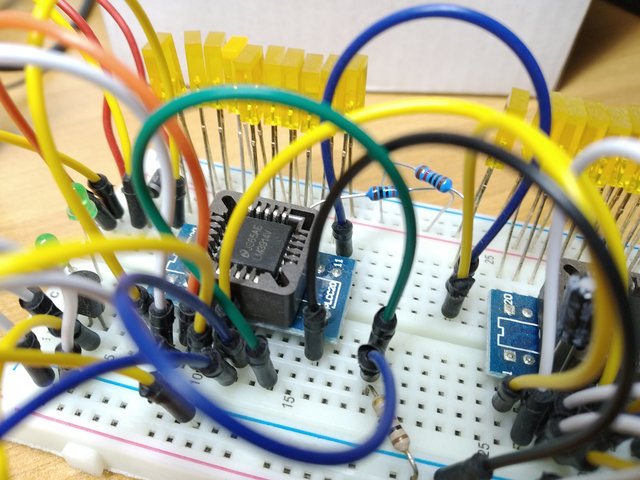
The following Fig. 3 is the circuit diagram for the prototype I’m going to build.

Building and testing
Carry issue
The prototype worked almost fine on the first attempt but there was an issue which I demo in the video below
You can see that when the input signal climbs, the carry function works fine but when the signal falls, instead of turning on the last LED of the first LM3914, it turns all the LEDs off (thus causing the green LED to go on) and then jumps down to the 8th or 7th LED. Same story for the 2nd LM3914.
After some reading frmo the datasheet about the “DOT MODE CARRY” which says
An auxiliary current source at pin 1 keeps at least 100μA flowing through LED No. 11 even if the input voltage rises high enough to extinguish the LED. This ensures that pin 11 of LM3914 No. 1 is held low enough to force LED No. 10 off when any higher LED is illuminated. While 100μA does not normally produce significant LED illumination, it may be noticeable when using high-efficiency LEDs in a dark environment. If this is bothersome, the simple cure is to shunt LED No. 11 with a 10k resistor. The 1V IR drop is more than the 900mV worst case required to hold off LED No. 10 yet small enough that LED No. 11 does not conduct significantly.
Note: in the citation above I replaced pin n.9 with 11 to match with the LM3914V which is the one I’m using for this project.
According to the explanation and the diagram in “Figure 14. Block Diagram of Mode Pin Description” I cannot explain what’s going on there. It seems to me there is some more trickery going on1 but adding a 10K resistor across LED 11 (and LED 21) fixes the issue as can be seen in video below.
Measurements
Here a few measurements from the final prototype with the following notes
- I didn’t have the resistors with the right values and wattage, so I used two potentiometers for R1 and R2
- I didn’t have a 2N2905 but rather a Panasonic 2SA1123.
- D1 is a 1N4007. Not a big deal.
- The LM3914V is not a TI original but rather some clone.
- Measurements were taken with my Solartron Schlumberge 7150plus which is in good working order, as far as I can tell, but not calibrated.
| Variable | Measured | Calculated |
|---|---|---|
| V+ | 6.1944V | 6.1V |
| Vref1 | 1.2500V | 1.25V |
| Vref2 | 2.4992V | 2.50V |
| Vref3 | 3.7461V | 3.75V |
| ILED | 12.00mA | 12mA (spec) |
| IR1 | 30.03mA | 29.9mA |
| ID1OFF | 0.91mA | 0.5mA (spec) |
| ID1ON | 10.49mA | N/A |
| ILM3914 | 29.19mA | 29.4mA (assumption) |
Conclusions
Here as well I’m pretty happy about how measurements turned out to be compared to calculated or assumed values.
With 0.91mA through D1 I can see the LED is barely emitting light and this is fine for that type of LED. If that were a high efficiency LED, then perhaps I would have had to change R1 in order to have it reasonably dim when it had to look off.
I’m thinking that a future build of this circuit should have a trimmer instead of a fixed value for R1 so that one can set the brightness of D1 when it’s on the off setting still keeping a correct current consumption of the LM3914’s.
Also R1 is getting pretty warm so I would recommend to have something like a fixed resistor of maybe 720Ω (1W) in series with a 200Ω trimmer also capable of dissipating at least 1W.
-
Perhaps there is some hysteresis in comparator C2 and the type of LEDs I’m using doesn’t make a clear cut between the two states of C2 making up for the issue. ↩